
Battle Centaur
- Mar 15, 2017
- 6 min read
Key Components
Controller(s):
CM-530
Actuators:
ROBOTIS Dynamixel AX-12W
ROBOTIS Dynamixel AX-12A
Sensors:
Touch Sensors (TS-10)
IR Sensors (Optional)
Power Source:
11.1V LiPo
Communication:
Zig-110A
Recommended Software:
R+ TASK
R+ MOTION
Solidworks
3D Files:
Solidworks & STL files
Program Files:
R+ TASK & MOTION files
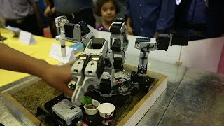
Introduction:
The Battle Centaur is a robot that can do battle in 3 unique game modes as well as competitively race in all of the game modes. The Battle Centaur can be customized with 3D printed parts that can be manipulated to fit your fighting and driving styles. Keep in mind that majority of the components can be attained from 2 kits: ROBOTIS PREMIUM and ROBOTIS PLAY 300.
Component List:
-Robotis Premium kit -Robotis Play 300 kit -Dynamixel AX-12W (recommended for maximum performance but can be substituted with an AX-12A from Robotis Premium kit) -Touch Sensor TS-10 - 3D printed parts (substitute available for base) - IR sensors (not necessary, but usable if desired)
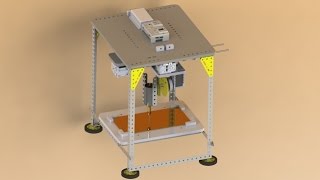
Instructions:
Step 1: The first thing that we will do is print out the base of the robot. We have attached the CAD files for the full base as well as two files that contain half of the base each so that the base can be printed in two halves and then epoxied together (see tutorial video for details on how to properly epoxy the base).The files labeled "3D printables" are prepared to be put into a 3D printer and work for this step and step 8. If you do not have the resources necessary to 3D print, then there is an alternative to printing using parts from the Robotis Premium kit (2x F52 & 2x F60). We have attached a CAD file and picture to show how these pieces can be attached and then screwed together. Step 2: Next we will have to attach the AX-12W actuators for the drive base. These must be attached in an exact order. If they are not attached in the same orientation the robot will not drive correctly. In the video tutorial there is a diagram that shows the correct orientation of the wheels (note: if you are using the alternative to the 3D printed base then you will want to thread the wires through the base before actually attaching the wheels since it will be difficult to fit them through after attaching the wheels, see step 10). Step 3: Now we will construct the torso of the robot. This is almost an exact replica of the torso of the Robotis humanoid A-Type robot that can be built using the Robotis Premium kit. You can download on your mobile device R+Design that can show step-by-step detailed instructions on how to assemble the humanoid A-Type robot under the premium kit tab. When looking at the assembly in R+Design on your mobile device it begins from the bottom of the robot, which is not what we need. Here are the steps that you will want to look at: For the assembly of the arms, follow steps 900-1144 & 1151-1395. For the Torso assembly, follow steps 1462-1631. While watching the assembly of the torso, do not pay attention to the parts where the torso is attached to the legs, the gyro sensor is attached, the battery is attached, or the DMS is attached since we will not be utilizing those parts of the humanoid robot. Our own tutorial video will demonstrate how the torso can be connected to an AX-12A (step 7). Also attached are pictures from the assembly manual that give added detail as to how to complete the torso. In addition to making the torso you will need to attach a Touch Sensor to the front of the torso using a F54 and touch sensor. In the tutorial video we will show how to attach the chest plate over the touch sensor so that it will properly work during battle. Step 4: Now we will construct the hip assembly. There is a portion of our tutorial video that deals with the assembly of this, but it will include the back pressure plate, the touch sensor, and an AX-12A. This will attach to the base and torso so that the torso can rotate independently of the base. Step 5: Next we will build the head and face plate. There is a portion of the tutorial video that shows the head and how it is attached. The head contains 2x F9, 1x F10, 1x touch sensor as well as a 5X7 and 3x7 plate from the play 300 kit. Step 6: Now we must attach the battery to the base. We need to attach the battery plate (F60) via 4 S1 screws and 4 N1 nuts. These attach at the back of the base and then the battery and battery compartment can slide on. This is also demonstrated in our tutorial video. Step 7: Now we need to attach the hip assembly and torso to the base of the Battle Centaur. To do this we will screw in four S3 screws into the F9 piece of the hip assembly. Do not forget to add the N1 nuts into the F9 slots. There is a portion of the tutorial video where we show how to attach the torso and hip assembly to the base. Step 8: You can also attach customizable 3D printable parts to your Battle Centaur. We have included a version of a sword and battle-axe in the files so that people can directly use those. In order to attach the hand held weapon and the shield. Just replace the S1 screws in the hand with longer screws as shown in the tutorial video. For the base weapon, you can decide if you want it on the front or back of your robot and just screw it into the Ax-12Ws at the base. This is also demonstrated in our tutorial video when we attach the "spinner" to our robot. Step 9: Now we need to wire the touch sensors. To do this you will need 3 wires (5Pcable-15 or 5P cable-40) and one of these ends will attach to the touch sensor and the other end into the controller. The port that you attach each of these to is very important since that is what the code for the robot revolves around so take care to ensure that they are plugged in correctly and fully. The head touch sensor connects to port (6), the chest goes to port (5), and the back touch sensor goes to port (4). Attaching the touch sensors is also demonstrated in the tutorial video. Step 10: The last thing to do is to connect all the dynamixels to the CM 530 controller using any combination of the cable-6, cable-10, cable-14, cable-18, or cable-20. We will start by wiring the arms to the controller. On each arm you must attach the furthest dynamixel closest to it, and then that arm into the controller. The port that you use on the controller does not matter so long as it is a DXL port. This method of connecting one dynamixel to another and then that dynamixel into the controller is known as a "daisy chain". This method can attach as many dynamixels together as necessary. After doing that to both arms, it should look like the picture of the arms, which we have included. Also inside of the chest are two dynamixels which will be connected in the same way as the arms. The order does not matter as long as they are both connected and one is connected to the CM-530. Now we will also attach all remaining dynamixels together by daisy chaining them together and then connecting just one to the controller. When daisy chaining dynamixels together it is just important to ensure that each one is connected to the chain and that you never have a loop that is not connected to the controller. After all the dynamixels are connected to the controller the Battle Centaur should be clear to run! Step 11: Quick note on operating the Battle Centaur. You first switch on the robot using the switch on the controller, and then you hit the start button beneath that switch. The Battle Centaur will now be in boxing mode, but you can change modes by pushing the (L) button for sword fighting, (R) button for jousting, and the (U) button for boxing if you have it in a different mode first. If your robot is ever disabled after losing and does the defeat motion then just hit the mode button that you desire and you can return to fighting! Step 12: Although the current code does not account for this, there are places on the front of the base that allow for three IR sensors to be placed as shown in attached pictures. As an advanced feature, people can attach these sensors to the base and add anything to the code so that the robot can utilize them to perhaps work better or more efficiently.


Comments