
Emu Bot
- Mar 15, 2017
- 4 min read

Key Components
Controller(s):
Raspberry Pi 2 Model B
ROBOTIS Open CM 9.04 A
Actuators:
ROBOTIS Dynamixel AX-12A
Sensors:
Raspberry Pi Camera
Power Source:
11.1V LiPo
Communication:
TP-LINK N600
Recommended Software:
N/A
3D Files:
EMU Showcase Zip
Program Files:
See 3D Zip file
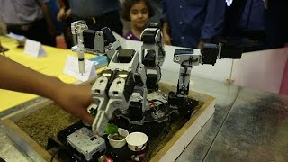
Introduction
A search and rescue robot created by Curtin University for The Confined Space Robotics Challenge. The purpose of this robot is to complete the following: Search and Rescue, Hazardous Materials Response, and Explosive Ordnance Disposal. Learn more at ww.confinedspacechallenge.org. Also, everything is open source and can be located at www.oarkit.intelligentrobots.org.
Components List
Dynamixel AX-12A x7
Raspberry Pi 2 Model B x1
Adafruit 3.5" 320x240 TFT
Wifi Adapter (i.e. TP-LINK N600)
ROBOTIS Open CM 9.04 x1
11 Volt Lithium Polymer (LiPo) battery x1
5A M205 Fuse x1
T80-T Switch x1
5V Output UBEC x1
Multiple 3-D printed parts - Body, Wheels, Camera Stand
Screw and Washers available at the ROBOTIS Store
DOWNLOAD ME FIRST
Step-by-step Instructions
Step 1
We will begin by constructing the body of the robot. The 3-D STL files will be located in this zip file. Download it and extract all the files. (3-D Printable Parts).
Step 2
After downloading all the parts.There are 2 ways to print the body.
1st: If you have a smaller 3-D printer (140x140x135 mm3)use this method. Open up the “Front Right Body” and “Front Left Body” files. Print 2 of each file for a total of 4 parts. They connect in order to form a rectangular body for the robot.
2nd: If you have a larger 3-D printer (200x200x150mm3) use this method. Open up the “FULL Body” file in order to print out the entire body. There is also another body “FULL Body” design that has holes compatible will ROBOTIS OLLO Bot parts. These can be used to further customize the robot. It takes longer to print out but is also a viable option.
Step 3
Print out 4 “Dynamixel Wheel” parts that will attach to Dynamixels 1,2,3,4 and act as wheels. You can add rubber-like material to the sides of the wheels in order to make it maneuver better.
Step 4
Print out the “Dynamixel Arm”, “Dynamixel Arm Base Left”, “Dynamixel Arm Base Left Washer” and “Dynamixel Arm Base Right” to attach to Dynamixel 5 on the bottom. The base parts will be screwed into the front of the body and attached to the wheel of the Dynamixel. The Arm will then be screwed onto the top of Dynamixel 5 and have Dynamixel 6 be screwed on top.
Look in the “Photos” folder for help.
MAJOR: When attaching the Dynamixel to the base make sure the single line on the Dynamixel lines up with the single line on the wheel when the arm is at a 90o angle with the body. In other words, when the Arm is vertical and standing up the single lines on the dynamixel should match and be facing downwards into the body. The double lines on the wheel should be facing upwards.
Step 5
Print out the “Dynamixel Wrist” and the “Dynamixel Wrist Washer” that will attach over Dynamixel 6 to act as the base for Dynamixel 7. This will allow the camera to move in almost all directions. Look in the “Photos” folder for help.
MAJOR: Same idea as in the previous step with the dynamixel. The single lines should match up when the wrist is at a 90o angle with the base.
Step 6
Print out the “Dynamixel Camera Mount” and the “Dynamixel Camera Cable Holder” . The Camera Mount will attach to the wheel of Dynamixel 7 and the Cable Holder will attach to the back of it. Look in the “Photos” folder for help.
MAJOR: Same idea again. The dynamixel should be lined up when the Camera is looking forwards.
Circuitry
Step 1
Attach the OpemCM 9.04 and Raspberry Pi on their respective sides on the top of the body.
Connect the ribbon cable to the camera and weave it through the arm to connect to the raspberry pi camera port.
Step 2
Daisy chain the top dynamixel of the arm (Dynamixel 7) to the bottom one (Dynamixel 5) until you reach the bottom of the arm. Connect that to the OpenCM 9.04 port on the bottom left (#1 in the picture).
Step 3
Solder in or use pins to connect the Analog from the OpenCM to the 4th from the top pin in the raspberry pi.
Connect the IN from the Open CM to the 5th from the top pin in the raspberry pi.
Connect the GROUND (GND) from the OpenCM to the 3rd from the top in the raspberry pi. Connect the top of the raspberry pi pin to the power of the UBEC.
Connect another wire to the 3rd from top pin to the ground of the UBEC.
(See Soldering and Circuit Pictures and for help)
Step 4
Connect the resulting power wire of the UBEC to the FUSE. From the FUSE connect a wire connecting the fuse and UBEC to a SWITCH. On the other end of the FUSE connect the ground of the UBEC to a BATTERY port.
Connect that BATTERY port’s power wire to the FUSE.
Connect the ground of the BATTERY port and the ground of the SWITCH to a pin that goes into the OpenCM top right port(#3 in the picture).
Step 5
Daisy chain all the wheel dynamixels and put the last one in the top left port of the OpenCM (#2 in the picture).
Step 6
Attach the adafruit touchscreen to the top of the pins where you first soldered all the wires underneath.
Step 7 Connect the wi-fi adapter to the usb port in the raspberry pi.
Programming
The following programs are located in the downloadable zip file.
(b_setID) (Default program provided by robotis to set up 4 Dynamixels)
(EmuBot_v3.ino) (sends Dynamixel status)
(EmuBot.py) (sends commands to OpenCM)
(student_starter.py) (tests to make sure that OpenCM and Raspberry Pi are working)


Comments